Ring Oscillator Design and Characterization In Cadence Virtuoso
2025-11-24 | By Mustahsin Zarif
Ring oscillators are a very important circuit design concept used for a variety of applications, including clock generators and random number generators. They are built using a chain of an odd number of inverters (NOT gates), with the output fed back to the input, resulting in an ever-oscillating signal. In this post, we will see how we can make our own ring oscillator in Cadence Virtuoso using 45nm technology.
Above, we see a schematic diagram of a 7-inverter chain ring oscillator that we want to design. The inverting function is easy to understand, but the interesting part of the oscillator is that the output from the final inverter that loops to the input is the logical opposite of the original input. This is why the oscillator can never reach stability.
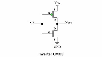
The first step to building the oscillator is to build an inverter first. An inverter is a PMOS in series with an NMOS, with a common input and output taken from the drains:
 Fig: inverter schematic in Virtuoso
At first, we use 120nm widths for both PMOS and NMOS in 45nm technology, but this might pose a problem: in theory, a PMOS is twice as bad at passing logic compared to an NMOS, so this inverter might not have equal pull-up and pull-down strength. We can verify this by keeping Vin = 0.5*Vout, sweeping the width of the PMOS, and measuring Vout.
 Fig: Vout vs PMOS width for inverter
 Fig: Vout vs Vin for an inverter with PMOS: NMOS width ratio = 140nm:120nm
We are using a power supply VDD = 1.1V, so the Vout of interest is 550mV. This is achieved at a width of 140nm. This is closer to 120nm and not 240nm from theory because technology has been evolving to make PMOS performance better. With the appropriate width found, we can reflect the change in our design:
 Fig: Inverter loaded with an inverter
This is a full schematic of the converter we tested, with 1.1V as the supply to the PMOS (to pass logic 1), ground connected to NMOS (to pass logic 0), and a Vin going into the gates of the inverters. Let’s convert it to a symbol so that it’s easier to use the inverter multiple times, make connections easily, and make it look compact:
 Fig: Inverter symbol
Great! Now, we can cascade 7 of these and build our oscillator! Wrong. I wish I could tell you it is that easy, but unfortunately, what happens as we add more and more inverters is that the load capacitance for the inverters near the input increases, so it gets harder for them to drive the loads. This is why we need to taper the inverter stages (increase their size). However, for the sake of simplicity, we skip the math for our design. Nevertheless, I want to show you the difference in propagation delays, and rise and fall times between an unloaded inverter and an inverter loaded with 1 inverter:
 Fig: propagation delay, rise time, and fall time for loaded vs unloaded inverter
From these two output boxes, we can see that the average propagation delay of an unloaded inverter (left) is 3.07765 ps whereas that of a loaded inverter (right) is larger at 4.78045 ps. Consequently, adding more stages will mean increasing the delay per inverter.
Going back to designing our inverter, this is what a symbolic arrangement of a ring oscillator looks like in Virtuoso schematic view:
 Fig: Ring oscillator with 7 inverters (n = 7)
 Fig: Transient response of ring oscillator with initial node voltage condition set to 0V
Here, the initial flat response is due to the fact that it takes some time for the input to propagate all the way to the output. Once it does, it loops back to the input, thereby beginning oscillations at a constant frequency of f = 1/(2tn), where “t” is the delay per stage (half a period), and “n” is the number of inverters. We can use Cadence’s built-in calculator to measure the frequency during oscillation times:
 Fig: frequency of oscillator
With the above-mentioned formula, we find our delay per stage to be t = 1/(2*7*9.05G) = 7.8897ps → much larger than the delay of an inverter loaded with 1 inverter!!
By now, we have learned how an odd number of inverters can be used to get an oscillatory output that can be used as a clock generator, among other applications requiring constant oscillations. Under the hood, we saw how to determine the ideal width ratios for PMOS and NMOS to get an inverter that is as good at passing logic HIGHs as it is at passing logic LOWs. Finally, we learned how to find the average propagation delay per inverter and understand the importance of increasing the size of inverters in the path from the input to the output so that the delay does not keep getting worse; this could significantly reduce the performance speed of devices.