Building a Dynamometer for the Openwheel Project - Part 1
2026-04-10 | By Zach Hipps
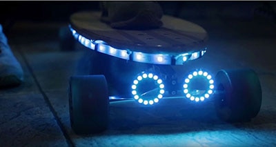
This is the Openwheel. It’s my open-source, DIY self-balancing board that I designed and built from scratch about five years ago, and I’ve finally decided it’s time to revive this project. In my last update, I did a teardown of a four-kilowatt hub motor just to see how it works, but if we’re going to make the Openwheel better, we need to actually understand how hub motors work, and more importantly, we need to be able to test them. So today, I’m building the first tool I need: a hub motor dynamometer.


First, I want to talk about the roadmap. This project is meant to be community-owned and driven. I already have a GitHub repository for the Openwheel, and as we build this together, it’s the perfect platform for version control and discussing issues. I want to be very clear, this isn't a product owned by Byte Sized Engineering or by me. I want this to be a community-designed product. That means we need collaborators. The goal for the Openwheel is total transparency. Eventually, I want us to design our own open-source hub motor, VESC controller, rails, and enclosures. We’ll iterate on the footpads, sensors, and battery management systems until the board is super reliable and enjoyable for everyone to build. The philosophy is simple. The board must be easy for a tinkerer to build, modify, and fix. While it requires experience to design, the assembly should be accessible. We’re also moving away from questionable parts. Instead of rolling the dice for critical electronics, we’ll be using reputable vendors like DigiKey to ensure reliability. My vision for the Openwheel is a “spectrum of building”. You should be able to go to a website, order a completed assembly, and just ride. Or you can download the files, order the PCBs, and manufacture everything yourself. The builder gets to choose how far down the rabbit hole you want to go.

To do my testing, I needed something sturdier than a temporary jig. I initially thought about retrofitting a bike trainer, but since I have a mountain of aluminum extrusion and a 3D printer, I decided to build an A-frame mounting structure from scratch. The assembly of the A-frame went smoothly, but connecting the hub motor axle to the bearings was a nightmare. I had an M8 bolt for the bearings, but the hub axle uses an M14 thread. I tried welding two different-sized nuts together to create a coupler, which gave me a lot of false confidence after the first one worked. The second one was a disaster. I got weld spatter in the threads and ended up stripping the bolt. I even tried welding the nut with the bolt already inside, which predictably welded the bolt to the nut permanently. I eventually moved to 3D printing. I designed a coupler with captive M8 nuts by pausing the print at a specific height. It looked great until the first test, where the plastic snapped instantly. I spent a week trying to get my CNC machine to cut a part from aluminum or maybe even acetal, a machinable plastic, but after some technical difficulties, I went back to 3D printing with beefed-up geometry and carbon-fiber PETG.


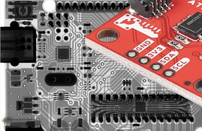
One of the hardest things about engineering is the "boring" parts. Hours of debugging code and tweaking valves that usually don't make the edit. I’m currently at a crossroads with the software. I spent days trying to get the VESC controller to read the I2C sensor directly so I could plot the data in the VESC Tool software, but I couldn't get it to cooperate. If anyone out there has experience connecting I2C sensors to a VESC and plotting that data, please reach out. Otherwise, my plan B is to use an external microcontroller, such as an Arduino, to read the load cell and talk to the VESC via UART. This is more in my wheelhouse and would allow me to write custom scripts for automated power tests.
If you want to help steer the direction of the Openwheel or just stay updated on the day-to-day progress, come join the conversation on our Discord server. It’s the best place to see the updates that don't make it into the big videos. We have a lot of work left to do on calibration and power measurements, but the revival is officially underway.